

Surgical Technique of Minimally Invasive Spinal System
01. Patient Positioning
02. Markings
03. Puncture
04. K-Wire Insertion
05. Dialator Insertion
06. Conventional Incision and Tapping
07. Screw and Extension Sleeve Assembly
08. Screwdriver Installation
09. Screw Insertion
10. Rod Measurement
11. Rod Bending
12. Rod Installation
13. Rod Insertion
14. Pre-locking
15. Compression and Distraction
16. Final Locking/Antitorque
17. Remove the Sleeve and Closure
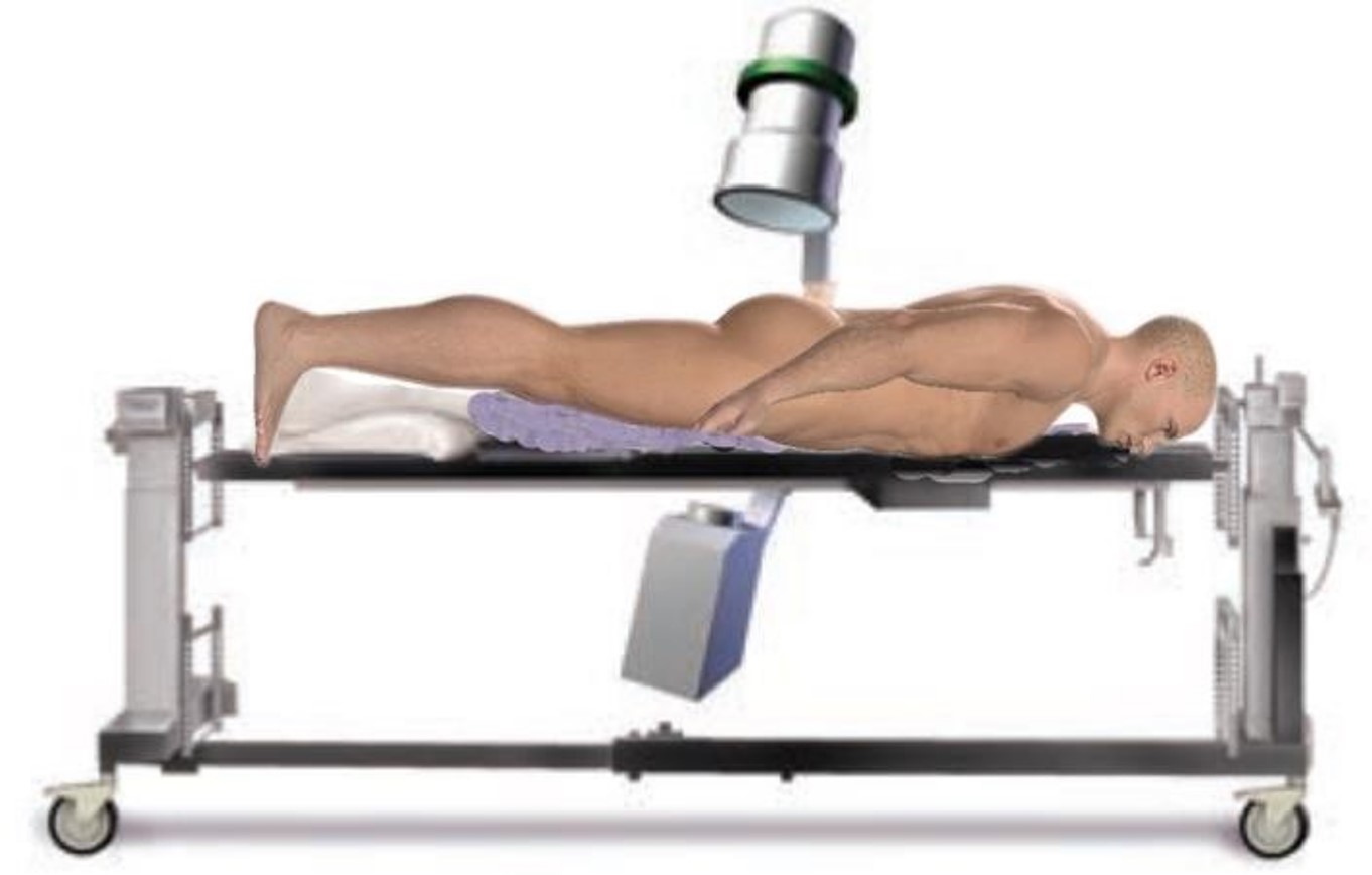
1. Patient Positioning
After general anesthesia for endotracheal tube, the patient should be positioned prone, lying flat on the fluoroscopic operating table.
2. Markings
Using standard fluoroscopy position, when the spinous process is located in the center of the bilateral pedicles, confirm the "oval" outline of the bilateral pedicles, and determine the entry point in the intersection of the outer edge of the pedicle shadow and the midline of the transverse process, then make markings on the skin at 4 to 5cm beside the spinous process usually.
3. Puncture
Insert the puncture needle through the skin, soft tissues to the bone of the pedicle. The puncture angle shoud be consistent with that of positioning.
4. K-Wire Insertion
After placing the puncture needle 0.5cm into the pedicle, remove the inner trocar of the puncture needle, and insert the K-Wire, then confirm the entry point and direction through fluoroscopy again.
5. Dialator Insertion
1) Incise the skin and fascia 1-1.5cm lengthwise.
2) Place the dilator over the K-Wire.
3) Place step sleeves to expand the skin.
4) The outer diameter of the gray sleeve can meet the needs of most surgical operations.
5) Hold the K-Wire in position when removing the dialator sleeve, and leave the outermost gray sleeve and the K-Wire.
6. Conventional Incision and Tapping
1) Place the opener over the K-Wire, and rotate it at the entry point, then remove it along the K-Wire after breaking bone.
2) Screw the appropriate tap into the pedicle over K-Wire, Note the scale markings on the tap and K-Wire in order to avoid screwing too deeply.
3) Hold the K-Wire by hand when removing the tap.
4) Use the scout to probe the screw pathway over the K-Wire to confirm that the pedicle wall is intact.
7. Screw and Extension Sleeve Assembly
1) Align the markings on the end of the screw with the markings on the top of the extension sleeve.
2) Insert the end of the screw into the head of the extension sleeve, there is a "click" sound to confirm that the insertion.
3) If the screw socket is opposite to the head of the sleeve, and the shrapnels on both sides cannot be reset correctly, you can open it manually for confirmation.
8. Screwdriver Installation
Place the screwdriver into the end of the extension sleeve, and insert the head of the screwdriver into the inner hexalobular groove of the screw, and tighten it.
9. Screw Insertion
1) Use the Ratchet Wrench to place the screw over the K-Wire and insert it into the pedicle.
2) The screw penetration depth can refer to the distance from the bone surface to the skin measured in the previous steps. The side wall of the sleeve has a length mark from the bottom of the screw socket to the skin. Do not put the screw socket close to the bone surface, otherwise the screw will lose its variable angle function.
3) Use the same method to insert other screws in sequence.
4) Turn the screwdriver knob to disassemble, and separate the screwdriver from the extension sleeve.
10. Rod Measurement
1) Insert the arc rod tester into the outermost extension sleeve, and the indicator reading is the required length of the rod.
2) The length of the rod should also take into account the increase in length caused by the expansion operation, otherwise the rod will not be locked properly.
11. Rod Bending
1) The product provides pre-bent curved rods and straight rods, which can be selected during the operation according to the needs of the patient’s condition. Since the screws provide a large swing angle range, the curved rods and straight rods can meet most of the needs, and the bending operation should be minimized.
2) If the condition involves a special location or anatomical structure, the special rod bending device provided by this system can be used. The rod bending device is provided with four levels of curvature. The slot on the side of the rod bending device can lock the titanium rod to ensure that it bends in the same plane, to avoid the difficulty of placing the titanium rod caused by the twisting of the titanium rod.
12. Rod Installation
Put the end of the rod into the corresponding slot of the rod holder, and use the rod holder wrench to lock the end of the connecting rod.
13. Rod Insertion
1) Adjust the directions of all extension sleeves so that the front notches are aligned lengthwise. And the outermost one needs to open outward.
2) According to the habit of the surgeon, choose one end as the starting point for the rod insertion, and turn the open side of the end sleeve (in the direction indicated by the arrow) toward the outside, otherwise the connecting part of the half-opening of the extension sleeve will hinder the insertion of the rod.
3) Place the rod along the sleeve into the bottom of the screw socket, turn the handle, and make the tip of the rod move slowly along the bone surface, and rotate the rod to a horizontal position gradually. In the process of inserting the rod, you can use the light source to observe the bottom of the sleeve or rotate the extension sleeve gently to confirm whether the connecting rod is in place.
4) The rod holder can be operated in or out of the slot of the extension sleeve.
5) Finally, the long handle of the rod holder is parallel to the outer wall of the extension sleeve, which can ensure that the connecting rod exceeds the screw socket by 5mm.
14. Pre-locking
1) Use a plug screwdriver to screw the screw plugs into the end of the screw one by one, and use a pre-tightening screwdriver to pre-tighten the screw plugs. Then unlock the rod holder and take it out, and screw in the screw plug.
2) The extension sleeve adopts a new threaded docking technology, and the rod can be directly placed into the screw socket with a screw plug.
3) There is a scale line in the middle of the pre-locking screwdriver, and the distance from the tail of the extension sleeve is the distance from the screw socket to the skin. After the connecting rod is placed to the bottom, the scale line should be flush with the top of the extension sleeve.
15. Compression and Distraction
1) According to the needs of the patient's condition, the compression or distraction operation can be realized.
2) The button at the end of the arc connector can be used to adjust the distance of the extension sleeve.
3) Choose one side as the fixed side, and use the pre-tightened screwdriver to reverse half a turn to loosen the plug on the other side.
4) Use compression pliers/distraction pliers to clamp/resist the outer wall/inner wall of the extension sleeve for compression/distraction operations.
5) Use a pre-locking screwdriver to tighten the screw plug after the pressure/expansion is finished.
16. Final Locking/Antitorque
1) Before self-breaking, it is necessary to confirm the position of screws, connecting rods, and fracture reduction etc. using fluoroscopy.
2) Put the opposing handle on the extension sleeve and tighten all the plugs in turn.
3) The screw plug will be stored in the self-breaking wrench after self-breaking, which can be operated continuously to improve efficiency.
17. Remove the Sleeve and Closure
1) Before removing the sleeve, check and confirm that the internal fixation is installed correctly, and there is no need to adjust it again.
2) Insert the unlocker into the sleeve, confirm the direction and depth, and hold it tightly to detach the shrapnels on both sides of the extension sleeve to realize the separation of the extension sleeve.
3) Lift up the unlocker and take the extension sleeve out of the body.
4) Loosen the unlocker to remove the extension sleeve.
5) After removing all the extension sleeves, close the fascia and skin with sutures.

